
Voltage and Current Measurement
Voltage current measurement
Introduction
A car's dashboard battery gauge and a phone charger's built-in protection circuit both need to continuously know two things, how much voltage is present and how much current is flowing, before they can make any safe decisions. In this experiment, a voltage sensor module and a Hall-effect current sensor module are both read by the STM32F070RB's analog to digital converter, and both measurements are printed together over UART.
2. Scope
This experiment covers reading two independent analog channels, converting a voltage-divider-scaled ADC reading back into the original, larger measured voltage, and converting a Hall-effect current sensor's offset analog output into a signed current value expressed in amperes. This combines the multi-channel ADC technique with two new engineering-unit conversions, voltage scaling and offset-based bidirectional current sensing.
3. Prerequisite
3.1 Hardware
-
STM32 Nucleo-F070RB development board
-
Voltage sensor module, resistive divider type
-
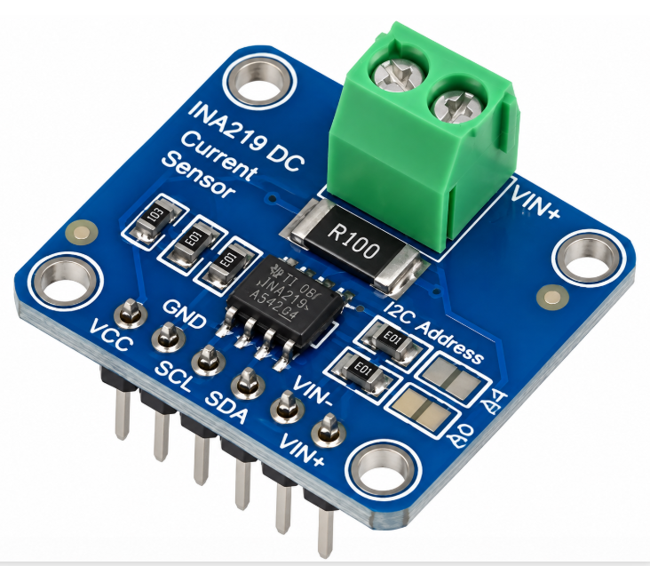
ACS712 or similar Hall-effect current sensor module
-
A DC load or source to measure, such as a small battery pack and resistive load
-
Breadboard and jumper wires
-
Micro-USB cable
-
PC with PuTTY
3.2 Software
-
STM32CubeMX (standalone)
-
STM32CubeIDE
-
ST-LINK USB driver
-
PuTTY, or an equivalent serial terminal application
Community Q&A
0 questionsAsk questions and get answers from our community and staff moderators.
No questions yet — be the first to start the conversation!
Ask a Question
Please log in to ask a question or post a reply.
Login to Participate